
Electron microscopy (EM) is a fantastic tool that enables biologists to capture images of their samples at a greater resolution than with a light microscope. There are several types of EM, and each of these can provide different information about your sample.
In this article, I’ll discuss the basics of the two main electron microscopy techniques, what information they can provide you, and end by comparing them. Because the field of EM is large and expanding all the time, there are a number of advanced techniques and instruments that I will not go into. I will provide links to relevant resources, however.
How Electron Microscopy Works: Key Terms Defined
Let’s start by defining some key terms that you’ll need to understand to develop your understanding of EM. Then, we’ll get into the two main EM techniques.
Magnification and Resolution
Often the term magnification is used when discussing the power of a microscope. However, magnification is not the main issue affecting microscopes. It is the resolution. Resolution is the ability to distinguish two objects as separate.
Put this article into practice
Choose a free resource to help you move forward

EBOOK
Guide to Special Stains for Histology

POSTER
Immunofluorescence Troubleshooting Guide
Imagine a car coming towards you at night. Initially, you would see a single headlight. At some point, you would be able to separate the light into two distinct headlights. This is the minimum resolvable distance or resolution.
In microscopy, we refer to the Airy disc, a diffraction pattern created by imaging a point object. The resolution of two objects in a microscope depends on them being sufficiently separate so that the diffraction patterns do not merge. This is known as the Rayleigh criterion.
Ernst Abbe was, in 1873, able to determine the optimum resolution that a microscope can achieve, and the equation for this is the Abbe diffraction limit. [1] Microscopes are designed to minimize variables so that the main limiting factor is the wavelength used to image the sample.
All types of electromagnetic radiation (e.g., visible light, X-rays, radio waves, etc.) have a characteristic wavelength. Using a type of electromagnetic radiation with a shorter wavelength increases the resolution that can be achieved.
For example, light microscopes can achieve a maximum resolution of ~200 nm because this is approximately the shortest wavelength of visible light. In fact, 200 nm is a bit shorter than the wavelength of blue light (~400 nm) but let’s not get into the hows and whys here.
Super-resolution light microscopy allows some biologists to go beyond 200 nm and X-ray microscopes do exist. However, EM remains the primary technique used by biologists for high-resolution imaging of molecules, viruses, and cells.
Electrons
Electrons are negatively charged sub-atomic particles that also possess a characteristic wavelength. They are crucial to both electron microscopy techniques. The wavelength of an electron is determined by the de Broglie wavelength and, in a microscope, is linked to the accelerating voltage (AV) used to generate the electron beam.
For example, an AV of 100,000 volts results in an electron wavelength of 0.0037 nm. This is ~100,000 times shorter than the wavelength of visible light. This in turn provides a higher resolution image of the sample (discussed below).
While it is possible to achieve sub-atomic resolution with an electron microscope, it is not possible to image biological samples at this resolution. Although cryo-electron microscopy is getting close. [2] Complex biological samples are usually the limiting factor!
Let’s take a look at the two main electron microscopy techniques.
Electron Microscopy Techniques: The Two Main Types
There are two main types of EM. They both have sub-techniques, but the two main types are:
- Transmission Electron Microscopy (TEM).
- Scanning Electron Microscopy (SEM).
The main differences between these are in their respective optics (Figure 1), how the signal is detected, and the type of information you can obtain.
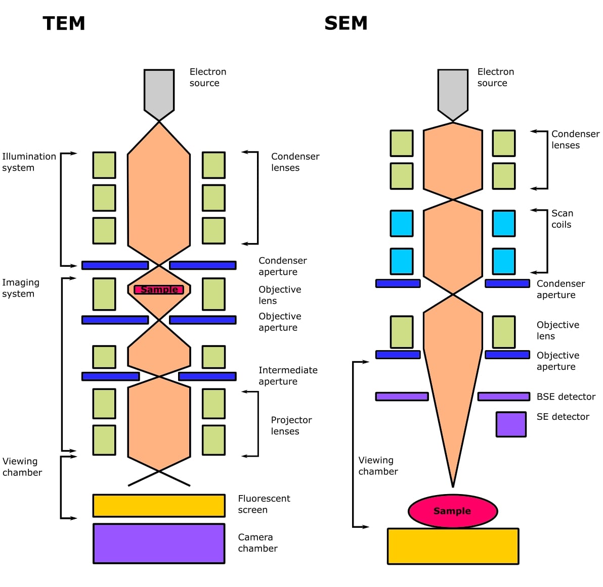
Both types of EM use an electron gun, which contains an electron source (a filament that produces a cloud of electrons), a Wehnelt cylinder (to form the beam), and an anode (to accelerate the beam).
There are three main types of electron sources:
- A tungsten filament.
- A lanthanum hexaboride (LaB6) crystal.
- A field emission filament/gun.
These technologies are used in a number of different sources. Their properties are summarized in table 1.
Table 1. Sources of electrons in electron microscopy.
Source Property | Tungsten filament | Thermionic | Cold field emission | Schottky field emission |
Material | Tungsten (W) | Lanthanum hexaboride (LaB6) | Tungsten (W) | Zirconiated tungsten (ZrO/W) |
Beam diameter | 1-2 µm | 1-2 µm | 3-5 nm | 10-25 nm |
Brightness (A/cm2sr) | 106 | 107 | 109 | 108 |
Energy range (eV) | 2.0 | 1.5 | 0.2-0.3 | 0.3-1 |
Resolution (nm) | <3 | <2 | <2 | <1 |
Both TEM and SEM use electromagnetic lenses to focus the beam of electrons. Electrons travel along the magnetic field and can be focused in the same way that light is focused using glass lenses, but using their negative charge instead.
The lenses have small apertures in them. These are thin plates of molybdenum that contain several small bores, usually in the range of 10-300 µm in diameter. Apertures are used in an EM to control the coherence of the beam, which affects resolution, and the amount of contrast in the signal.
Transmission Electron Microscopy Explained
The Transmission Electron Microscope (TEM) is the original form of electron microscopy. It was developed in 1931 and requires electrons to be transmitted through the sample. A high voltage electron beam is emitted by a cathode source and controlled by magnetic lenses.
This electron beam is then partially transmitted through a thin specimen (Figure 2). And I mean very thin! So thin that electrons can pass through it!
The electrons are subsequently diffracted by the sample specimen. Then, electromagnetic lenses re-focus the beam into a Fourier-transformed image of the diffraction pattern for the selected area of investigation.
The condenser lenses (2-4 depending on the microscope) are responsible for the amount of illumination that reaches the sample and control beam intensity or brightness.
The objective lens focuses the beam of electrons onto the sample and applies a small amount of magnification. The intermediate and projector lenses magnify the beam and project it onto the detector to form the final image, which is called a micrograph.
How Long Does TEM Imaging Take?
It takes only a few seconds to obtain a micrograph. Electrons are detected as light areas in the micrograph, while darker areas occur where electrons have been scattered or absorbed by the sample, which reduces the number of electrons reaching the camera or screen.
This is known as bright field imaging and is the most common type of imaging for biological samples.
What Makes a TEM Microscope More or Less Powerful?
By convention, TEMs are often classified based on the AV they are capable of achieving. A routine TEM for biological imaging should be capable of an AV up to 120 kV. Most thin-section TEM experiments are conducted at 80-100 kV. Advanced TEM techniques may require instruments capable of an AV between 200 kV and 3 MV, which can generate a ~ 2000-fold increase in magnification than a light microscope. Nice!
This extreme resolution is why TEMs are typically used for viewing internal atomistic features inside or beyond the surface of a sample (e.g., internal features organelles, and macromolecules).
Limitations of TEM
The main limitation of TEMs is that they produce two-dimensional, black and white images. In addition, you cannot image living samples. This is because, among other things, the processing needed to cut your sample into 10 nanometers is harsh and will kill a living sample.
Scanning Electron Microscopy Explained
Scanning Electron Microscopy (SEM) was invented in 1942. Unlike the TEM, at no time does SEM carry a complete image of the specimen. Whereas in TEM, the electrons in the primary beam are transmitted through the sample, SEM produces images by detecting secondary electrons that are emitted from the sample surface due to excitation from a primary electron beam (Figure 2).
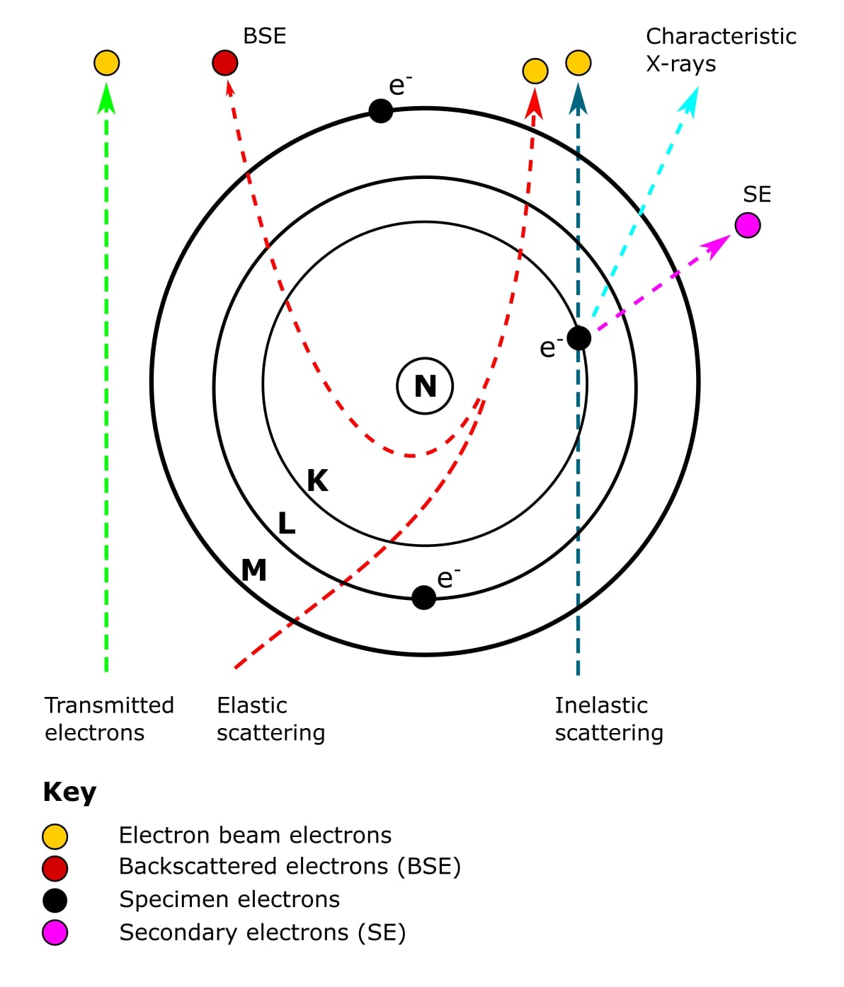
Oh, and secondary electrons are low-energy electrons produced by small energy transfers between electrons from the primary beam and electrons orbiting atoms in the sample. It is these electrons that are picked up by the detector to produce the final SEM image.
So, SEM works by rapidly scanning the surface of your sample with a focused electron beam. This causes electrons to be knocked off the surface of your sample. These are your secondary electrons and are what encode information about the sample.
Examples of the information they encode include surface topography and composition. And the types of samples you can study include the surface of a housefly’s eye and human inner ear hair cells.
SEM Samples Need to Be Sputter Coated
Also, samples in SEM must be conductive. Most biological specimens aren’t intrinsically conductive, however. To overcome this, samples are coated with a thin layer of a conductive element such as gold. This process is called sputter coating.
A full appreciation of SEM requires a bit of a deeper understanding than this, however. So let’s get technical.
How Imaging with SEM Works
A scanning electron microscope focuses a beam of electrons into a small spot that scans across the surface of a sample. A condenser lens assembles the electrons into an ultrafine beam, and the objective lens focuses this beam onto the sample.
Deflection coils cause the beam to move in a rectangular X and Y direction, producing a raster scan (hence scanning) across the surface of the sample.
An SEM image is formed from signals that are emitted from the sample as a result of the specimen-beam interactions (Figure 2).
Most biological SEM experiments will generate images using two types of electrons.
The first type of electrons we’ve already mentioned. Energy transfer between the electron beam and sample surface causes the orbiting electron to leave the atom. These are the secondary electrons mentioned earlier. An outer orbiting electron will then release some energy as it falls into the gap left by the secondary electron.
The second type of electrons is called backscattered electrons. These are high-energy electrons that have passed close to an atomic nucleus and been reflected or “backscattered” out of the specimen (Figure 2).
To complicate things a bit further, there are a few applications that require the detection of characteristic X-rays (Figure 2). These include energy-dispersive X-ray spectroscopy and cathodoluminescence.
Don’t worry if this all sounds complicated. Basically, all these fancy electron types originate from different places within atoms on the surface of the sample. And because they have different energies, they are produced at different depths within the sample (Figure 3). The types of electrons detected determines the nature of the SEM experiment and instrumentation. Simple!
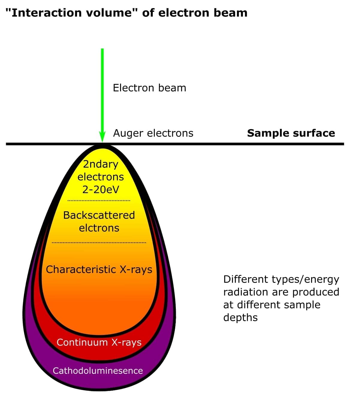
Finally, the resolution of an SEM image depends on the spot size of the beam as it hits the sample and the interaction volume between the beam and specimen. The interaction volume directly relates to the AV of the beam. Biological SEM experiments typically use an AV of 1-5 kV for the best resolution.
Similarities and Differences Between TEM and SEM
That’s a lot of information to digest so let’s have a quick comparison of these electron microscopy techniques.
An SEM image is inverted compared to the TEM. Bright areas of the image are the result of more electrons being scattered. However, both images are grayscale.
Relatively large biological samples can be imaged using an SEM as we no longer have to transmit the signal through the specimen.
Similarly, because an SEM image relies on electron interactions at the surface, it can image thicker samples and boasts a much greater depth of view.
Both may not be used to observe living specimens as the entire microscope, including the sample, must be in a vacuum in order for the image to be formed.
Both SEM and TEM microscopes:
- Are very expensive to buy and maintain.
- Require stable high-voltage and currents supplies.
- Need continuously-pumped ultra-high vacuum systems.
- Are very sensitive to vibration and external magnetic fields.
- Require considerable sample preparation.
Check out the Bitesize guide to sample prep for SEM here and read about fixing samples for TEM here.
What about the differences between SEM and TEM? I’m guessing by now you’re a bit word-ed out, so here’s a handy table.
Table 2. Differences between SEM and TEM.
Aspect/feature | TEM | SEM |
Developed in | 1931 | 1942 |
Classification of electrons used | Transmitted electron beam | Scattered (backscattered or secondary) electrons |
Image formation process | Fourier recombination of electrons that are scattered by the sample | Detection of, primarily, secondary and back-scattered electrons from the sample surface |
Focus of analysis | Internal or beyond the surface (e.g., viruses, organelles, atoms, macromolecules) | Surface of the sample |
Image presentation | 2-D | 3-D |
Magnification | Up to 50 million magnification level | Up to 2 million magnification level |
Resolution | 0.5 Ångströms | 0.4 Nanometers |
Special sample preparation | Sample must be cut extremely thinly | Sample must be stained or coated with an element that generates secondary electrons (e.g., gold) |
And by the way, electron microscopes are delicate (and did I mention they’re expensive?) So be sure to speak to your resident microscopist to arrange training before jumping on one!
Electron Microscopy Techniques Summarized
Hopefully, you now have a working understanding of the two main electron microscopy techniques, how they differ, and what samples are appropriate to each of them.
Want to know more about electron microscopy? Discover the history of cryo-EM, and understand the developments that have allowed near-atomic resolution.
Electron microscopy is a huge and active area, however, so be sure to add your wisdom in the comments section below!
Originally published July 2016. Reviewed and updated March 2022.
References
- Abbe E (1873) Beiträge zur Theorie des Mikroskops und der mikroskopischen Wahrnehmung. Archiv für mikroskopische Anatomie 9:413–18.
- Dillard RS, Hampton CM, and Strauss JD et al. (2018) Biological Applications at the Cutting Edge of Cryo-Electron Microscopy. Microsc Microanal 24:406–19
You made it to the end—nice work! If you’re the kind of scientist who likes figuring things out without wasting half a day on trial and error, you’ll love our newsletter. Get 3 quick reads a week, packed with hard-won lab wisdom. Join FREE here.
Put this article into practice
Choose a free resource to help you move forward
POSTER
Immunofluorescence Troubleshooting Guide

POSTER
Fluorescent Proteins Guide


