Sometimes the biggest hurdle to mastering a new topic is mastering the vocabulary. To help you master optical fibers I put together this illustrated glossary of Optical Fiber Vocabulary. Read this along with my first article “Introduction to Optical Fibers” and you will be well on your way to mastering optical fibers.
Acceptance Angle
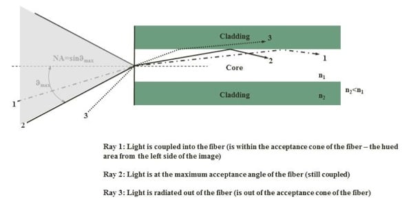
The half-angle of the cone (Θmax in Figure 1) within which incident light is totally internally reflected by the fiber core. Applies only to MM optical fiber though!
Figure 1.
Add/Drop Multiplexing (ADM)
A device (optical element of optical fiber) that allows lower level signals to be added or dropped from a communications network (high-speed optical carrier) in a wire center [wavelength division multiplexer (WDM) transmission]. The connection to add/drop multiplexer is via a channel to a central office port at a specific digital speed (DS3, DS1, STS, etc.). Illustrated below in Figure 2. Tx=transmission of a signal, Rx=Reception of a signal.
Figure 2.
Angled Physical Contact (APC)
A type of fiber optic connector with a 5-15 angle-polished end surfaces of the connector tip to minimize backreflection. In Figure 3 the angle for APC configuration is 5÷15º.
Figure 3.

Armor
A protective layer of corrugated steel, wrapped around a cable. To prevent rodent attacks. Used in both buried and aerial applications.
Arrayed Waveguide Grating (AWG)
A device, built with (silicon) planar light wave circuits (PLC), which allows multiple wavelengths to be combined and separated (multiplexed and demultiplexed) in a dense wavelength-division multiplexing (DWDM) system. See Figure 4.
Figure 4.

Attenuation Coefficient
A coefficient characterizing the attenuation of an optical fiber per unit of length (dB/km). This coefficient corresponds to the rate of optical power loss with respect to distance along the fiber.
Back Reflection (BR)
The power reflected back toward the source in the optical link (fiber ends, fiber deformations, and connectors). Also called Fresnel reflection. See a Figure 3.
Bandwidth
The range of frequencies within which a fiber optic or a terminal device can transmit data or information.
Bandwidth – Distance Product
The frequency range that can be transmitted by the optical fiber expressed in MHz×km. Bandwidth determines the maximum transmitted information capacity of a channel that can travel unperturbed along the optical fibers over a certain distance. This is almost distance-unlimited in single-mode optical fiber, but narrow in number of frequencies, whereas is distance-limited in multimode OF (due to the modal dispersion), but large in number of frequencies.
Bend Radius
The smallest radius an optical fiber or fiber cable can bend before excessive attenuation or breakage occurs.
Bit Error Rate (BER)
The average fraction of transmitted bits that are received incorrectly. The BER of a system for optical fiber communications is influenced by noise, optical losses, dispersion, and nonlinearities.
Buffer
In optical fiber, a protective coating applied directly to the fiber.
C-Band
The wavelength range between 1530 nm and 1562 nm used in some CWDM (Coarse Wavelength Division Multiplexing) and DWDM (Dense Wavelength Division Multiplexing) applications.
Carrier-to-Noise Ratio (C/N)
The ratio of the received carrier strength to the strength of the received noise (in dB) before any nonlinear process such as amplitude limiting and detection takes place. High C/Ns provide better quality reception, and generally higher communications accuracy and reliability, than low C/Ns.
Circulator
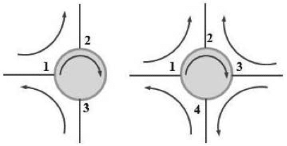
A passive component composed of three or four ports that couples signal from one port (n) to the next port (n+1). The first port being is counted as following the last one and port n is isolated from signals in port n+1. See Figure 5.
Figure 5
Cladding Mode
Cladding mode is an undesired light ray mode that propagates in the cladding, see effective area definition.
Coarse Wavelength Division Multiplexing (CWDM)
CWDM is a method of combining multiple (minimum 8) signals/channels at various wavelengths in the 1550 nm region of optical fiber (the C-Band, vide infra). The number of channels is fewer than in dense wavelength division multiplexing (DWDM) but more than in standard wavelength division multiplexing (WDM).
Obs: CWDM systems have channels at wavelengths spaced 20 nm apart, compared with 0.4 nm spacing for DWDM.
Cleave
The process of separating an optical fiber by a controlled fracture of the glass, for the purpose of obtaining a fiber end, which is flat, smooth, and perpendicular to the fiber axis
Composite Power
The sum of the power level of each carrier of a DWDM system.
Conventional Band (C-Band)
Wavelength transmission band from 1530 to 1565 nm. Also called third window.
Cross-Phase Modulation (XPM)
The change in the phase of a signal caused by the interaction with another signal. The phenomenon is due to nonlinear Kerr optical effect occurring in the fiber and causing a change of the refractive index.
Crosstalk (XT)
- Undesired coupling from one circuit, part of a circuit, or channel to another.
- Any phenomenon by which a signal transmitted on one circuit or channel of a transmission system creates and undesired effect in another circuit or channel.
CTS (“clear to send”)
In a communications network, a signal from a remote receiver to a transmitter that it is ready to receive a transmission.
Cutback Method
A technique to measure the attenuation of an optical fiber by comparing the optical power transmitted through a fiber to the power transmitted by a short section of the same fiber.
Cutoff Wavelength
The wavelength beyond which a single-mode fiber carries only one mode/The wavelength below which the fiber ceases to be single-mode.
Data rate
The number of bits of information in a transmission system, expressed in bits per second (b/s or bps), and which may or may not be equal to the signal or baud rate.
Decibel (dB)
Unit used to express values of power (intensity) level on a logarithmic scale. The power level is always relative to a reference power P0: where P and P0 are expressed in the same linear units.
Demultiplexer (Demux)
A device that separates two or more signals previously combined (see Figure 3).
Dense Wavelength Division Multiplexing (DWDM)
A technique used to multiplex several signals on a single fiber within a narrow wavelength band. For example: the transmission of many closely spaced wavelengths in the 1550 nm region over a single OF. Wavelength spacing is usually 100 GHz (0.8 nm) or 200 GHz (1.6 nm). DWDM includes C-Band, S-Band, and L-Band (vide infra).
Dispersion-Shifted Fiber (DSF)
A type of single-mode fiber designed to have zero dispersion near 1550 nm. This fiber type is not suitable for DWDM applications, due to its high nonlinearity at the zero-dispersion wavelength.
Diplexer
A device that combines two or more types of signals into a single output. Usually incorporates a multiplexer at the transmit-end and a demultiplexer at the receiver end.
Distributed Feedback Laser (DFB)
An injection laser diode built with a Bragg reflection grating in the active region in order to avoid multiple longitudinal modes and enhance a single longitudinal mode. It produces a finer range of wavelengths than a Fabry-Perot laser, are often used in DWDM communication where a tunable laser signal is desired.
Distribution System
Part of a cable system used to carry signals from the head-end to subscriber terminals.
Double-window Fiber
1) Multimode fibers: optimized for 850 nm and 1310 nm operation. 2)Single mode fibers: optimized for 1310 nm and 1550 nm operation.
Dynamic Range
A characteristic of an Optical Time Domain Reflectometer (OTDR). Depending on the noise level reference, there are a couple of definitions:
- IEC Dynamic Range (introduced by Bellcore) where the upper level of the noise is taken as the upper limit of a range, which contains at least 98% of all noise data points.
- RMS Dynamic Range is the root mean square (SNR=1) dynamic range that corresponds to the difference between the extrapolated point of the backscatter trace at the near end of the fiber (taken at the intersection between the extrapolated trace and the power axis) and the RMS noise level. This determines the maximum observable length of a fiber and, therefore, the OTDR suitability for analyzing any particular network.
Effective area (EA)
Area of the fiber corresponding to the mode field diameter. See Figure 6.
Figure 6.
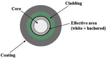
EA determines the power density of the light injected into the fiber, ie small EA ? high power density ? important nonlinear effects. The EA of a standard single-mode optical fiber is around 80?m, and can be as low as 30?m for compensating fibers. The value of EA is included usually in the description of the fiber’s name.
Equilibrium Mode Distribution (EMD)
In multimode fibers, EMD is a steady state mode distribution. When achieved, the relative power in modes is stabilized and the distribution of light travels in the medium without any disturbance or leakage/gain.
Equilibrium Length (equilibrium coupling length, equilibrium mode distribution length)
The length of multimode fiber necessary to reach the equilibrium mode distribution for a specific excitation condition. Also called equilibrium coupling length and equilibrium mode distribution length.
Encircled flux (EF)
The ratio between the transmitted power at a given radius of the core and the total injected power.
Figure 7.

EF is related with the power distribution inside the fiber core, the spot size of the light source (LED, VCSEL, and laser) and the alignment of the beam into the fiber. All of these are called ‘launching conditions’. Launching conditions affect attenuation in the fiber. An ideal situation is illustrated in the second image in Figure 7 above. .
Equilibrium Mode Distribution (EMD)
The steady modal state of a multimode fiber in which the relative power distribution among modes is stabilized and independent of fiber length (light travels in the medium without any disturbance or leakage/gain). The spot diameter is around 70% of core diameter.
Equilibrium Length (equilibrium coupling length or equilibrium mode distribution length)
The length of multimode fiber that is necessary to reach the equilibrium mode distribution for a specific excitation condition.
Extended Band (E-Band)
A transmission band for wavelength from 1360 to 1460 nm.
Extinction Ratio
The ratio of the low/OFF optical power to the high/ON optical power, expressed as a percentage [(PL/PH) x 100].
Extrinsic Loss:
In a fiber interconnection, the portion of loss due to imperfect joining of a connector or splice.
Eye Pattern
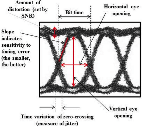
An oscilloscope display that allows several system performances measurements. The “openness” of the eye relates to the BER that can be achieved. The vertical eye opening indicates the noise level in the system: the more it is opened the less noise level. The horizontal eye opening is related to the amount of jitter in the signal: the wider the opening, the less jitter. At higher data rates the profile thickens. See Figure 8.
Figure 8.
Well that is it for this part of the alphabet. Be sure to check out next month forIllustrated Optical Fiber Glossary (F-Z).


