Using fluorescent proteins as imaging probes is a widespread and versatile technique in microscopy. You can use them in a wide range of living systems, from single cultured cells to complete organisms and animals. Fluorescently tagged proteins can be used to track and examine real-time localization, interactions, and translocation of your protein of interest, as well as determine the relative expression level, which will be proportional to the fluorescent intensity under experimental conditions and specific systems.
Tagging with a Fluorescent Protein
The most common method of tagging a protein of interest is to fuse your fluorescent protein (‘FP’) to the cDNA of your gene of interest. The in-frame cloning of a gene of interest with an FP results in a genetic construct, which can be transferred into your cells or organisms using a plasmid or virus vector. You can perform this to generate either a ‘transient’ or ‘stable’ expression. Transient transfection results in an expression of the genetic construct (usually in the cytoplasm) over a relatively short period of time, typically up to 72–96 hours after transfection. In stable transfection, your FP-tagged protein gene can be incorporated into the genome of the cell of interest resulting in a permanent and stable cell line.
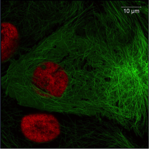
Figure 1. Image of Pig Kidney Epithelial cells (LLC-PK1). green: Tubulin-eGFP, red: h2b-mCherry; Imaged with ZEISS LSM 800 with Airyscan. Images taken with permission from ZEISS’s Flickr page.
Although transfection usually does not affect the localization, function, and expression of the target protein, there can be problems in each of these areas of normal function. Here we’ll discuss what to look out for and how to remedy these issues to ensure you get the best out of your fluorescently tagged proteins.
Problems With incorrect Localization or Function
Sometimes the addition of a fluorescent protein will affect the localization or function of a protein; after all, you’re adding a tag that is fairly large (GFP is 27 KDa). Therefore, you should always check you get the correct localization and the function is not affected. If either of these is altered there are a few things you can try:
Check with EGFP
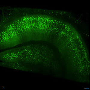
Figure 2: Thy1-EGFP M-line mouse hippocampus. Imaged with ZEISS Lightsheet Z.1. Images taken with permission from ZEISS’s Flickr page.
Enhanced fluorescent green protein (EGFP) has the highest and most predictable performance of all fluorescent proteins and as such, it is recommended that you carry out a pilot study using EGFP before tagging your protein of interest with your choice of FP. Better still, use the FP called ‘mEmerald’, which is an EGFP that has enhanced brightness and photostability. Such pilot studies should ensure your protein of interest is spatially expressed and functions as normal. For more information on EGFP, see this interactive tutorial over on ZEISS Campus.
Choose a Correct Linker
One of the possible problems encountered with abnormal localization or function of your fluorescently tagged protein is the amino acid linker that links your FP to your protein of interest. Glycine is the recommended choice of linker since it has the smallest side chain and the greatest degree of flexibility. In general, the linker should be between 2– 10 amino acids long to ensure correct folding of both the FP and target protein.
N or C terminus?
Another important consideration is the placement of your FP in relation to your protein of interest. The amino (N) or carboxy (C) termini of your protein may be responsible for determining the localization or specific interactions, so fusion of the FP to either end may affect function and localization. Before deciding on fusion at either the N or C terminus, you should consult the literature and extrapolate which strategy works best for similar target proteins. You might even find someone who has done this with your exact protein of interest.
Figure 3: EGFP linked to the N-terminus of Human Alpha Tubulin. Image reproduced with permission from ZEISS’s Campus.
If there is an issue due to fusion, this can be improved by the insertion of a flexible glycine-rich linker between your FP and target protein. In some cases, both the N and C termini of the target protein are involved in localization and interactions, in which case the FP can be inserted in a side-chain of the target. Another option is to insert the FP in the middle of the sequence such as within highly flexible loops or where there is a sequence of relatively disordered amino acids.
The fusion terminus of your FP also needs careful consideration. In general, EGFP and other green fluorescent protein (GFP) variants from the Aequorea species of jellyfish are usually fused at their flexible C-terminal ends which have a sequence of around 10 amino acids. The N-terminus of these FP’s require a longer linker and are less tolerant of fusion. If the FP you wish to use is derived from reef-building corals, then these are more accepting of fusion at the N-terminus.
Lack of Expression or Low Expression?
Aggregation and Accumulation
Many fluorescent proteins have a tendency to oligomerize and this can result in aggregation in cases where your protein of interest also oligomerizes (such as actin or tubulin) oligomerization of FPs can inhibit the correct formation of oligomers. Luckily there are mutants of GFP and GFP-derived FPs that are purely monomeric, so if you observe aggregation and accumulation you may want to switch to one of these. Coral-derived FPs, unlike those derived from GFP, have a low pKA value meaning that they can fluoresce in the highly acidic lysosomes. Therefore if you observe aggregation and accumulation of coral-derived proteins it is likely caused by transport of the FP fusions to lysosomes for degradation. This may be due to very high expression levels, so consider decreasing the transfection amounts if this is observed.
Codon and Sequence Issues
Many of the FP cDNAs are either native species or have been codon-optimized for the intended host cell. If you are having issues with low expression in the transfected cells, this may be due to codon bias. Don’t worry – codon-optimized variants are available for most mammalian, plant, and fungal cells.
Another consideration is Kozak sequence issues. The Kozak consensus sequence is a sequence that occurs on eukaryotic mRNA and plays a major role in the translation process. This sequence is 5?-ACCATGG-3?, where the internal ATG is the initiating methionine (Snapp, 2005). If you are having expression problems ensure that a Kozak sequence is present, and if so check that the flanking sequences of the fusion gene are not interfering with translation or transcription.
Factors Affecting Expression or Signal Strength
pH
Even with EGFP fusion and all of its modifications, you might still encounter low levels of fluorescence. One of the factors that can affect the expression of pH sensitivity is pH sensitivity. Wild-type GFP has been shown to be pH sensitive (Shaner et al., 2005; Snapp, 2005) and some cell organelles have pH ranges that differ from that of the cytoplasm and can interfere with the detection of FPs. Organelles such as lysosomes, secretory granules, and the Golgi have a relatively low pH and if your protein of interest localizes to these, then it is recommended to use an FP that has a relatively low pKa value such as those derived from corals.
Choice of Fluorescent Protein
Choosing a stable FP that will in turn produce a strong and localized signal is a crucial factor to consider following an EGFP pilot study. This is a somewhat complex (and not fully understood) consideration when designing your experiment. The photostability of your FP will be in part determined by the detection system you use to image the transfected cells or organisms. The intensity and source of light, coupled with the excitation wavelengths are just some of the factors which will determine the behaviour of an FP (Chudakov et al., 2010).
Figure 4. Spectral profile for excitation and emission for GFP and GFP derivatives. Image reproduced with permission from ZEISS Campus.
The easiest approach is to compare the spectral profile of several FPs using the same excitation wavelength and light source. This should aid in choosing the most photostable FP for use with your specific excitation and detection system.
To compare FPs of different colors requires a slightly more complex approach and is based on the photobleaching half-time to reduce the emission rate to 50% from an initial rate of 1,000 photons per second for each FP (Chudakov et al., 2010). Although the brightest protein would appear to be the most desirable simply due to the photon output, you should use this method with caution, as many factors within the cell will contribute to the final brightness of your FP. In addition to choosing an FP based on the above information, data from the literature should also be used when making your decision. Has someone previously created an FP-tagged version of your protein? If so try using the FP and conditions they have to save time, although remember you may still need to perform some optimization and should still determine that the localization and function is not affected.
Fluorescent Protein-induced Cytotoxicity
A final factor to consider when examining expression is the possible cytotoxic nature of some FPs. Certain FPs can accumulate in lysosomes which can then form cytotoxic agglomerations (Chudakov et al 2010). As before, it is helpful to consult other studies to determine if the FP of choice is able to generate stable cell lines or can be used safely in transgenic animals. Although is it relatively rare for FPs to have apparent cytotoxic effects, with an increasing number of FPs available to researchers, it is unknown whether some will be more toxic than others, but, as always, it is recommended to carry out pilot studies and use appropriate controls.
For more information on practical aspects of fluorescent proteins, head over to ZEISS Campus.
References:
- Chudakov D.M., et al. (2010) Fluorescent proteins and their applications in imaging living cells and tissues. Physiological Reviews, 90:1103–63.
- Shaner N.C., et al. (2005) A guide to choosing fluorescent proteins. Nature Methods, 2:905–9.
- Snapp E. (2005) Design and use of fluorescent fusion proteins in cell biology. Current Protocols in Cell Biology, July 2005, Chapter 21.


