Introduction to Optical Fibers, Part 1
Everybody’s talking about them, tens of millions use them, but do you know anything about optical fibers/cables? Well you should. In this first (of many) articles I will cover the basics of optical fibers, what they look like and what they are made of.
Optical Fiber Anatomy
First thing first, the terms “optical fiber” and “optical cable” are not interchangeable. Optical fibers refer to the individual, very thin, highly transparent strands/pipes of dielectric material (or semiconductor, in years past) that carry light along their lengths. Optical fibers could also be called “optical waveguides” in that they guide light. While optical cables refer to groups of optical fibers in numerous numbers, arrangements, and designs.
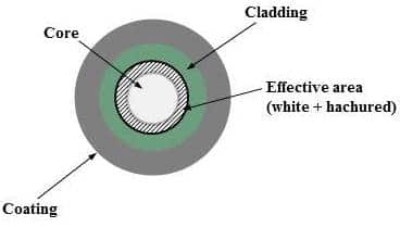
An optical fiber is made of three parts (see Figure 1):
- The core, which is the center part of the fiber, carries the light signal.
- The cladding, which is the middle layer and is typically 125 ?m (0.005 inch) in diameter, keeps the light in the core.
- The coating, which is the outermost layer, protects the cladding.
Figure 1:
How Optical Fibers Work
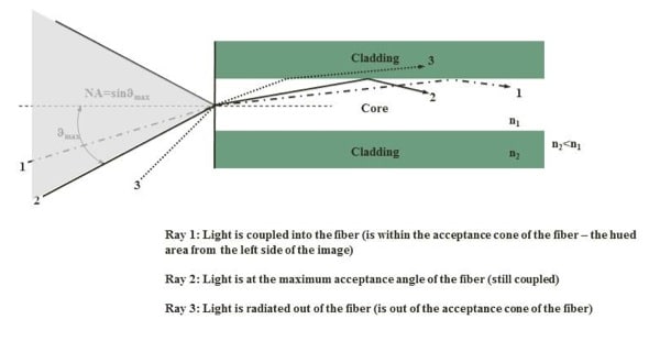
Anytime we talk about light, it seems refractive indexes come up, and optical fibers are no exception. The core and the cladding of optical fibers have different refractive indices. The core has a higher index of refraction than the cladding. Therefore when light enters the core (within the acceptance cone) it stays inside the core due to total internal reflection phenomenon (vide infra). In this way the light can be guided inside the fiber and transmitted forward, like in a tunnel.
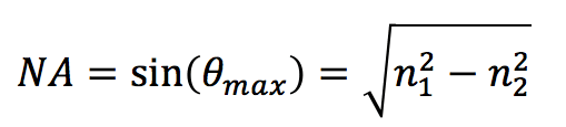
Okay so let’s talk more about this acceptance cone (hued area in the Figure 2). Not just any light will get trapped in the core of an optical fiber. Instead only light rays at or beyond the critical angle will be reflected at the core-cladding interface. Thus, as in microscopy, there is a numerical aperture (NA) for optical fibers that measure the acceptance angle of light that a fiber can support through total internal reflection:
Another formula for NA is in terms of the relative refractive index difference:
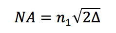
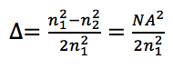
Figure 2
Where n2 is for the cladding and n1 is for the core. Typical values for NA are between 0.2 and 0.5 for multimode fiber, and 0.05 to 0.4 for single-mode fiber (vide infra). Delta has values between 1 and 3%. The larger the numerical aperture, the more the light is coupled into the fiber. But this produces modal dispersion, which causes pulse spreading (bandwidth limitations).
The light emerging from a fiber is also in a cone. This cone is known as the emerging cone. For best coupling results, the acceptance cone and the exit cone should be approximately the same, as is the case of the single-mode fibers (vide infra).
Types of Fiber
There are many types of optical fibers, classified according to various criteria. But the main classifications are according to the materials that make up the core and the cladding:
Type 1: Glass Optical Fiber (GOF).
GOF are made of glass cores and glass cladding. The cladding is usually made of very pure silica or fused quartz, while the core is usually silica doped with germanium or phosphorus to increase the refractive index
Type 2: Plastic or Hard Clad Silica (PCS/HCS).
PCS are made of a glass core and plastic cladding. The glass core is often vitreous silica, and the cladding is usually a silicone elastomer with a lower refractive index.
Limitations of PCS
- It has considerable plasticity making connector applications difficult.
- Adhesive bonding is not possible.
- It is insoluble in organic solvents.
Type 3: All-plastic fiber (POF)
POF are made of a poly-methylmethacrylate (PMMA), polystyrene (PS) and polycarbonates (PC) core; and a fluoropolymer or silicone resin cladding. Today per-fluorinated polymers (cyclic transparent optical polymer) are used. They have transmission windows in the visible region (520–780 nm), and transmission losses due to absorption and scattering of light are high, ranging from 150 dB×km-1 for PMMA to 1000 dB×km-1 for PS and PC. As such, POF can only be used for short-distance data transmission or applications up to 100 m.
Advantages of POF
- The light-guiding core has a large diameter (about 1mm). Making it easy to connect across joints and align.
- It is more mechanically flexible (elastic) than another options. Making it the perfect choice for extremely confined application environments. This also means that it is resistant to cracks and insensitive to mechanical shocks.
- It is easy to modify you can shorten them to any length just using a knife.
- Light.
Limitations of POF
- It has a lower bandwidth than GOF. Meaning that it has a lower data transfer rate.
- It is less efficient than Silica fibers.
- It has a high attenuation (>1dB/m). This means that the useful/wide spread applications for POFs are in illumination, sensing, low-speed connections, and for short distances.
- Flammable.
I hope you now feel comfortable with the basics of what optical fibers are made of and how they work. Make sure to come back for part 2, where I will discuss the basic types of OF: single mode, multimode, step and graded index, and some new configurations.